Home
›
Technical Data
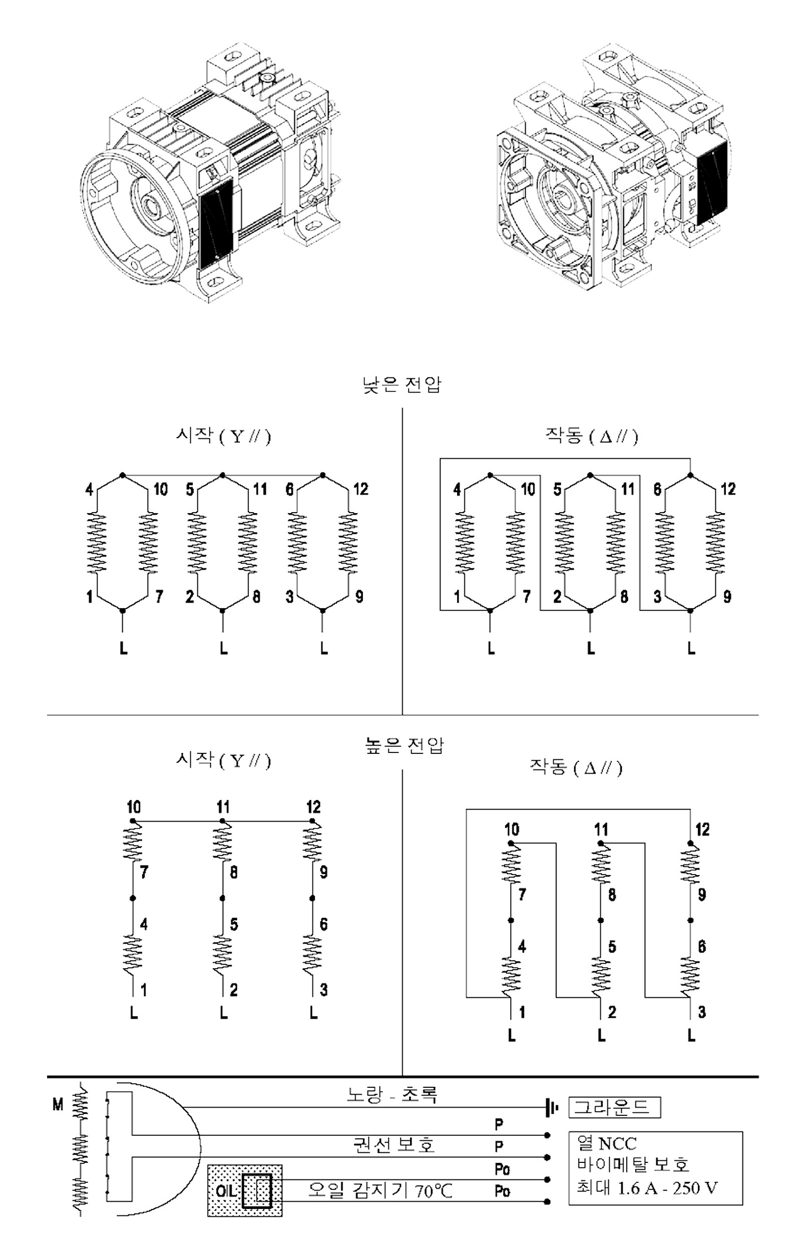
Hydraulic motor wiring diagram
⬇ Download PDF
(328KB)
Low voltage
Start ( Y // )
4
10
1
7
L
5
11
2
8
L
6
12
3
9
L
Run ( Δ // )
4
10
1
7
L
5
11
2
8
L
6
12
3
9
L
High voltage
Start ( Y // )
10
7
4
1
L
11
8
5
2
L
12
9
6
3
L
Run ( Δ // )
10
7
4
1
L
11
8
5
2
L
12
9
6
3
L
On a phone, swipe sideways.
M
Ground
Yellow - green
P
P
Winding protection
OIL
Po
Po
Oil sensor 70℃
Thermal NCC
Bimetal protection
Max. 1.6 A - 250 V
View the original image
Tap the image to enlarge it.